
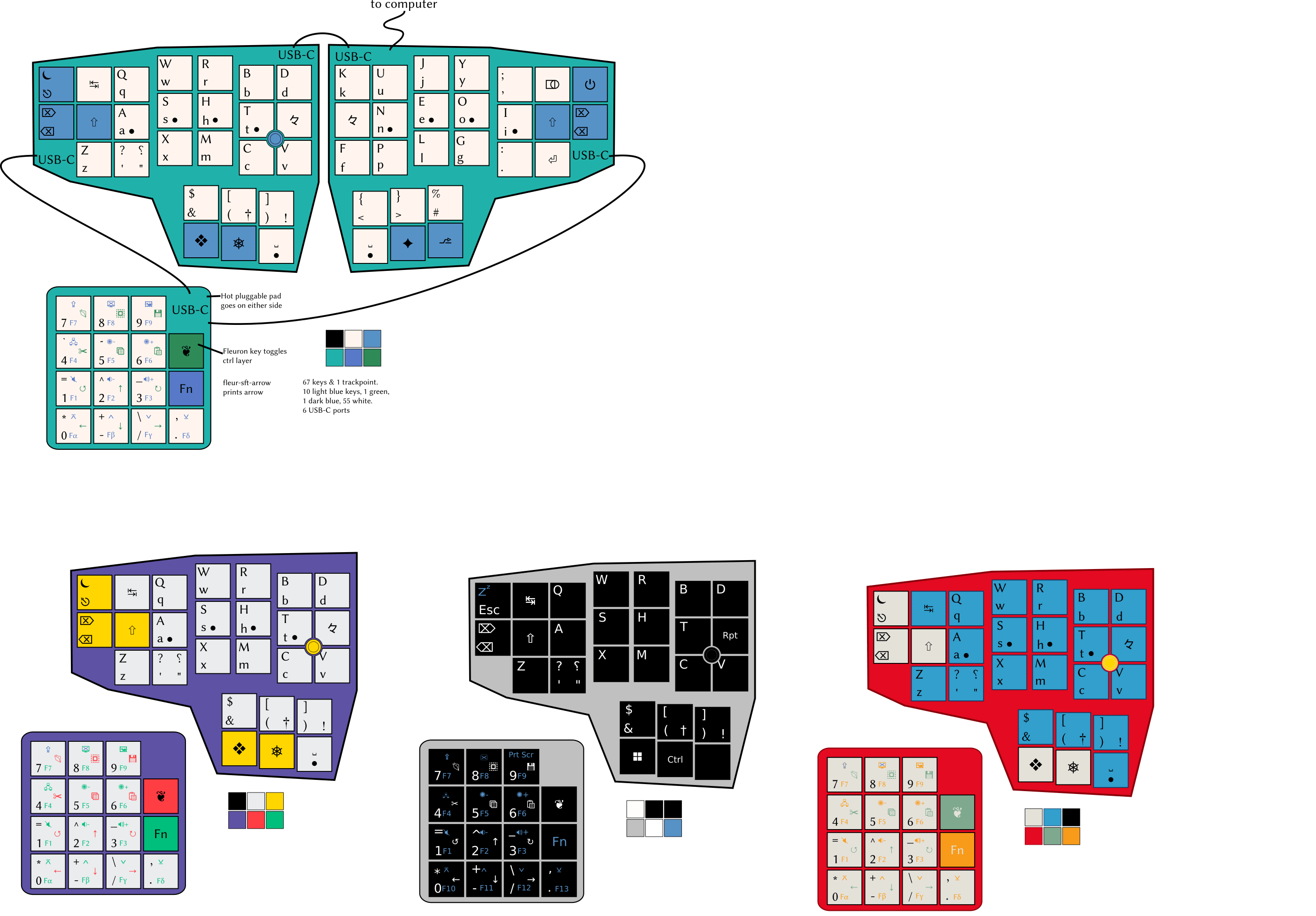
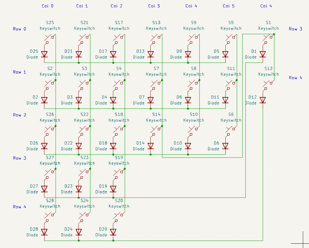
Here’s what the layout should look like when it’s done, and what the schematic for the right half looks like now. I’ve seen Joe Scotto’s tutorial on the subject.
I’m currently making a schematic for this keyboard in KiCad v7.0. The schematic has the power & backspace keys moved down near the thumb keys to use one fewer pin on the controller, hence the slightly messy wiring.
- What controller should i use for a keyboard like this? How many more pins will it need than just the 5 columns and 6 rows on each side?
- What USB connector ports should i use? What are the differences between one USB-C port and another?
- Do i need a controller for each part of the keyboard, or only for the part that plus into the computer?
- Where can i get KiCad files for a trackpoint so i can add that to the schematic and PCB?
- I’ve only ever owned one mechanical keyboard (Chouchou by dlip) and it doesn’t look like it has any diodes. Do i need those or not?
- Can i hide the controller and ports in a case if i’m using low-profile switches and caps?
Thanks in advance.
Electrical engineer here. I can only answer a few of the questions:
This will be a “USB Device” (as opposed to USB Host or USB OTG) so the correct USB connector to use is B receptacle, mini-B receptacle (obsolete), micro-B receptacle (obsolete), or C receptacle. You can pick any one of those. The obsolete ones still work fine, it’s just hard to find cables for them. Mini-B is actually very durable. Alternately, you could have a captive cable with a USB A male plug on the end.
KiCad has pretty good facilities for making your own component layouts. Many components you simply can’t find existing files for. Unfortunately, this is part of the life of circuit design. It should only take an hour or so per component.
Adding diodes can enable N-key rollover. If you don’t need that feature, you could skip it. If you’re going to the trouble of making your own keyboard, diodes are a comparatively small cost, so you should do it. The Chouchou keyboard uses a separate pin for every single key, so it doesn’t need diodes.
Yes, you can hide the parts in a case. But you could also just make the back of the circuit board really long, and there should be enough space for it. Picking out connectors and cables and stuff is always a pain, so try to avoid having multiple boxes if you can. The electronics should be pretty small anyway.
Actually, I just saw that the image could zoom in if I opened it in a new window.
Regarding your connectors: If you want to have the different parts of the keyboard connect by USB-C, then you would need to add a USB-C hub inside each part that could have downstream devices.
If you are willing to have each part be a different USB device, that would simplify the design a lot. Then, they could all connect to a USB hub.
If you want to minimize cable clutter, you might consider interconnecting the components with something like QWIIC, which is pretty small. It would also require doing custom firmware.
For these split keyboards, the more common thing is to use the functionality built into the custom firmware to have them act as a single USB device. It’s particularly important here as the small number of keys mean there are lots of things going on with layers and macros, so having the two halves talk to each other is quite important.
With the easy availability of wireless-capable controllers, fully wireless splits are becoming more common, but for now the most common way to connect the halves is with a TRRS 1/8” audio cable or a repurposed 4-conductor USB port, as the firmware can send what it needs between the halves with 4 wires.
That’s not to say people (and companies) aren’t doing more involved and creative things with hubs and base stations and the like, just that it’s not necessary to have a split keyboard that operates as a single device with one USB cable to the host and one “USB” cable connecting the halves.
I wanted to use USB-C so everything is hot swappable. From what i’ve read audio cables aren’t great for that.
I do have a USB hub already so i could just make these 3 separate boards instead of a 3 part split. It would mean a few more wires on my desktop but i don’t mind that too much. Especially if i make the pad wireless.
The problem you might run into is that if you connect everything “properly” via USB, they are separate, discrete devices. In many ways, that’s fine. People have multiple keyboards attached while testing things. Separate numpads and macropads basically are this. The challenge you are going to run into with the two main halves of your keyboard are that if they are discrete USB HID devices, they cannot share any modifiers that are not built into the OS. So like, “Shift” and “Control” will work fine, but “FN1” and “Fn2” and anything you code outside the “normal” HID protocol will be quarantined to that half of the keyboard. You couldn’t, for instance, hit a layer-shift key with your left hand and tap F11 with your right.
I agree with the other poster that to make the numpad piece truly modular, integrating a hub of some sort will work. I would just say the two halves of your split keyboard need to work together as a single device, one way or another. ZMK is built for wireless keyboards, so that might be the first place to go looking.
Finally, while I’m personally deeply fond of builds that include numpads, many folks who go ergo do it specifically to keep their hands from flying across multiple devices, so they figure out how to do numerical entry and navigation on the main units of their split device.